Tuesday, March 06, 2007

FDISK

This is the main screen used during the time running FDISK. This would also be the first screen if your computer operating system does not support FAT32. From this window you will have the capability of setting up or removing partitions from your hard drive(s).


------------------------------------------------------------------------------------------
Using the options within this screen you will be able to create the various different partitions. These options will only allow you to create FAT16, and FAT32 partitions if supported and you pressed Y for Yes to enable large disk partitions. If you are attempting to create NTFS partitions, use Windows NT Disk Manager.

1. Create Primary DOS Partition - Choosing this option you will be prompted to use maximum space. If you specify yes, this will use up to 2 GB if creating FAT16 partitions, or up to 32 GB if using FAT32. If you choose no you will be able to specify how large you would like the partition to be. NOTE: you will need to create primary partitions before being able to create Extended or Logical DOS partitions.2. Create Extended DOS Partition - If you are using FAT16 and have a 2 GB or higher hard drive or have only specified a small portion of the hard drive as the Primary partition, use this option to create the Extended DOS partition(s) (other drive assignments). The Extended DOS partition will be used to hold the Logical DOS drives; therefore, use the maximum space left on the hard drive.3. Create Logical DOS Drive(s) in the Extended DOS Partition - This option is used after you have created an Extended DOS partitions. Once the Extended DOS partition has been created you then can specify the sizes of other partitions you wish to create.Example of what has been explained above:Bob has a six GB hard disk drive and wishes to divide the hard drive into three partitions, each using FAT 16.Step 1. If prompted to use Large Disk support, press N for no because Bob does not want FAT32, he would like FAT16.Step 2. Choose option one to create a Primary partition. Once prompted to use maximum space, press N for no and specify 2 GB as the size of the primary partitions Step 3. Once the primary DOS partition has been created, choose option two to create an extended DOS partition. Use the maximum space, which would be four GB because two GB has already been used for the Primary Partition.Step 4. Create two logical DOS drives, each being 2 GB.Step 5. Reboot the computer and format each of the drives to allow them to be accessible.Assuming Bob only had one hard drive, doing the above Bob would have:Drive C: Partition 1 (Primary) FAT 16Drive D: Partition 2 (Extended/Logical) FAT16Drive E: Partition 3 (Extended/Logical) FAT16Note: Once a primary partition has been created please ensure that you set the partition as an active partition.
-----------------------------------------------------------------------------------------------
Within this screen you will have the capability of deleting pre-existing DOS partitions. If you currently have no disk space available on your hard drive and wish to create additional partitions, you must first use this screen to delete the partitions and then you will be able to create partitions. NOTE: if you delete partitions, any information on those partitions will be erased and CANNOT be recovered.
1. Delete Primary DOS partition - Use this option to delete your main primary partition. However, if you currently have any Extended / Logical DOS partitions, you must delete these partitions before you will be able to delete the Primary DOS partition.2. Delete Extended DOS partition - If you have your computer partitions into more than one drive, use this option to delete the extended dos partition(s). You must delete the Logical DOS Drive(s) before you can delete the Extended DOS partition.3. Delete Logical DOS Drive(s) in the Extended DOS Partition - This option would be used first if you have extended DOS partitions and wish to delete the extended partitions.4. Delete Non-DOS Partition - This option is usually used for partitions that either have been created by third-party applications, such as a DDO or other operating systems such as IBM Warp, Unix, as well as various other operating systems.Example of what has been explained above:Bob has created three partitions on one hard disk drive; however, he would like to delete them all.Step 1. Delete the two logical DOS drive(s) in the Extended DOS partition with Option number three.Step 2. Once the Logical DOS partitions have been deleted, choose option number two to delete the extended DOS partition.Step 3. Choose option one to delete the Primary partition.Step 4. Reboot the computer to allow above changes to take effect.
------------------------------------------------------------------------------------------------
Within this screen you will be able to see what is currently being used and how your computer hard drive is setup. NOTE: If you see invalid information such as !, *, &, % as the Volume Label, the Partition, or the Status, it is a good possibility that you may have a VIRUS on the computer.


The above picture displays information about Extended DOS partitions; if, however, you only have a Primary DOS partition, your screen would only display the partition information and you will only have the option to Esc out of the screen.
------------------------------------------------------------------------------------------------This option is only available if more than one Hard Drive is installed within the computer. In the below picture you can notice that we have 3 hard drives listed within this computer. Disk 1 has two partitions, which are C: and D: The hard drive's total space is 3 GB. Then Disk 2 has three partitions E:, F:, and G: and the hard drive total space is 6668, or 7 GB. As you notice in the below picture, there is also a Disk 3, this is actually an Iomega Zip Drive hooked up to the IDE controller on the Motherboard. Other media that is connected to the IDE controller within your computer will usually be displayed within FDISK; however, this is not a hard drive and does not need to be FDISKed, this is why 95MB is free. An exception to this rule would be a CD-ROM.


Wednesday, January 10, 2007

Latest Model of a Motherboard


EPoX 5EDAI — a Motherboard on Intel 915P
Intel 915P chipset (i915P Northbridge and ICH6 Southbridge)
The motherboard market has come to a standstill on the threshold of models based on the new line of Intel 965 chipsets. Indeed, the entire computer world is waiting for the appearance of Intel Core 2 processors in desktops. These processors with the new microarchitecture are officially supported only by i965/975-based motherboards. (i975X is quite an expensive chipset without unique features; besides, not all first revisions of motherboards will work with Conroe.) So during this lull we'll publish reviews of old motherboards that we missed. We'll also expand our horizons, as we have been pointed at a growing number of reviews about products from a limited number of manufacturers.
EPoX 5EDAI returns us to the past. To the i915P chipset, which was launched nearly two years ago… Many lances were broken over the sudden upgrade to new Intel standards. DDR2 memory was expensive and slow, no one wanted PCI Express and that stupid socket… But now this budget motherboard from EPoX arouses no feelings of inferiority. Fortunately, such memory got cheaper (DDR2-533 is nearly cheaper than DDR400), all new video cards are designed for PCI Express only, and no one remembers how the old socket looked like. 5EDAI is a budget solution, but it does not mean that this solution is bad. This model offers flexibility in memory usage (two slots for DDR and two for DDR2 — of course, four slots of the required standard would have been better, but different users need different things) and peripheral slots: 3 x PCI (all of them will be available even after you install a monstrous video card), 2 x PCIEx1, one graphics slot (how many of your friends have a SLI/CrossFire computer?). Additional controllers are kept to minimum, but there are some nice features (like an integrated POST controller), passive chipset cooling, and as a result - a low price. This model also has drawbacks, of course — it does not support dual-core processors (all cores newer than Prescott) and DDR2-667 memory (and higher), but it's a questionable drawback. Scanty functionality has a good effect on the PCB layout: there are absolutely no problems with arranging a few connectors for peripheral devices and expansion cards. IDE and FDD connectors are located behind PCI slots to facilitate access in a small PC case, but memory slots stand in lone conspicuity, which certainly makes it easy to handle them. A main power connector in the center of the board is a peculiarity of most EPoX models, which has a positive effect on voltage regulators, though it poses some problems with laying a power cable. Besides, this connector is very close to the PCIEx16 slot on this motherboard, so it will fight for the surrounding space with a video card with a bulky heatsink. Access to jumpers is not hampered when the motherboard is installed into a PC case. But both of them are placed close to other elements: one of them is near a PCI slot, the other - to the display of the POST controller. So it's not very convenient to manipulate them. Brief description of their functionality is provided on the PCB (sometimes in unexpected places).
The 4-phase switching voltage regulator of the processor incorporates seven 1800 uF capacitors (Luxon) and four 560 uF ones (Sanyo). The motherboard is also equipped with a voltage regulator for memory, reinforced with L elements and several 1000 uF capacitors. The PCB has empty seats for a chassis intrusion sensor and a connector for a Game port on a bracket. It may be a peculiarity of our sample, as the PCB of this model is unique in the line of EPoX products. Other motherboards from this company, based on the same chipset family, usually offer better functionality (Gigabit Ethernet + RAID of SATA drives + IDE RAID) and designed for DDR memory (support for two memory types is a unique feature of the 5EDAI). Motherboard dimensions — 305x245 mm (full-sized ATX, nine-screw mount, all motherboard edges are firmly fixed).
System monitoring (Winbond W83627THF, according to BIOS Setup)
CPU core, memory, chipset, battery voltages, +3.3 and +12 V and +5 V Standby
RPM of 3 fans
CPU and board temperatures (by the corresponding embedded sensors) and an external thermal sensor, which is connected to a special header on the PCB — EPoX remains one of the few companies that still include this useful feature into its models; unfortunately, our bundle lacked the thermal sensor
Chassis Smart Fan Control — automatic control of rotational speed of a system fan depending on a temperature inside a PC case (this function is mostly for offices, you can specify a desired temperature within 35—55°C)
CPU Fan Auto Control — "classic" CPU fan speed control depending on CPU temperature (the budget model uses the simplest method: you specify desired temperature, the other parameters are configured automatically).
Onboard ports, sockets, and connectors
Processor socket (Socket 775, officially supports all modern Pentium 4 (5xx/6xx series) and Celeron D (3xx series) processors, permissible bus clock — 533/800 MHz)
2 x DDR SDRAM DIMM (up to 2 GB DDR200/266/333/400, dual-channel mode supported) and 2 x DDR2 SDRAM DIMM (up to 2 GB DDR2-400/533, dual-channel mode supported) — different memory types cannot work together!
PCIEx16 for a video accelerator
2 x PCIEx1
3 x PCI
Power connectors: standard ATX 2.2 (24 pins, you can use a usual 20-pin connector), 4-pin ATX12V connector for a processor
1 x FDD
Chipset-based IDE connector (Parallel ATA) for two ATA100 devices
4 x "chipset-based" SATA (Serial ATA) for four SATA150 devices
2 connectors for brackets with 4 additional USB ports
1 x CD/DVD audio connector
AUX-In connector
S/PDIF-In/Out
Connectors for analog audio ins and outs on the front panel
IrDA connector
3 fan headers, all of them support rpm control, one of them is a 4-pin header (for a processor fan) offering more accurate fan speed control (if this option is supported by a cooler).

Monday, December 04, 2006

PARTITION and FORMATINGI

Important If you follow these steps on a hard disk that is not empty, all the data on that hard disk is permanently deleted. We recommend that you back up your hard disk before you follow these steps.

To partition and format your hard disk by using the Windows XP Setup program:
1. Insert the Windows XP CD-ROM into your CD-ROM drive or DVD-ROM drive, or insert the first Windows XP Setup disk into the floppy disk drive, and then restart the computer.

Note To start your computer from the Windows XP CD-ROM (or from the startup disk), your computer must be configured to start from the CD-ROM drive, the DVD-ROM drive, or the floppy disk drive. In some cases, you may have to modify your computer's BIOS settings to set this configuration. For information about how to configure your computer to start from the CD-ROM drive, the DVD-ROM drive, or the floppy disk drive, see the documentation that is included with your computer, or contact the computer manufacturer.
2. If you are starting the computer from the Windows XP CD-ROM, select any options that are required to start the computer from the CD-ROM drive if you are prompted to do this.

Note If your hard disk controller requires a third-party original equipment manufacturer (OEM) driver, press F6 to specify the driver.

For more information about how to use F6 to supply a third-party OEM device driver while the Windows Setup program is running, click the following article number to view the article in the Microsoft Knowledge Base:
314859 (http://support.microsoft.com/kb/314859/) Limited OEM driver support is available with F6 during Windows XP Setup
If you are starting from the Windows XP Setup disks, insert each of the additional disks when you are prompted, and then press ENTER to continue after you insert each disk.
3. At the Welcome to Setup page, press ENTER.
4.
Note If you are using the Setup disks (6 bootable disks), the setup will prompt you to instert the Windows XP CD.
5. Press F8 to accept the Windows XP Licensing Agreement.
6. If an existing Windows XP installation is detected, you are prompted to repair it. To bypass the repair, press ESC.
7. All the existing partitions and the unpartitioned spaces are listed for each physical hard disk. Use the ARROW keys to select the partition or the unpartitioned space where you want to create a new partition. Press D to delete an existing partition, or press C to create a new partition by using unpartitioned space. If you press D to delete an existing partition, you must then press L (or press ENTER, and then press L if it is the System partition) to confirm that you want to delete the partition. Repeat this step for each of the existing partitions that you want to use for the new partition. When all the partitions are deleted, select the remaining unpartitioned space, and then press C to create the new partition.

Note If you want to create a partition where one or more partitions already exist, you must first delete the existing partition or partitions, and then create the new partition.
8. Type the size in megabytes (MB) that you want to use for the new partition, and then press ENTER, or just press ENTER to create the partition with the maximum size.
9. Repeat Steps 4 and 5 to create additional partitions if you want them.
10. If you want to install Windows XP, use the ARROW keys to select the partition where you want to install Windows XP, and then press ENTER. If you do not want to format the partition and install Windows XP, press F3 two times to quit the Windows Setup program, and then do not follow the remaining steps. In this case, you must use a different utility to format the partition.
11. Select the format option that you want to use for the partition, and then press ENTER. You have the following options:
Format the partition by using the NTFS file system (Quick)
Format the partition by using the FAT file system (Quick)
Format the partition by using the NTFS file system
Format the partition by using the FAT file system
Leave the current file system intact (no changes)
The option to leave the current file system intact is not available if the selected partition is a new partition. The FAT file system option is not available if the selected partition is more than 32 gigabytes (GB). If the partition is larger than 2 GB, the Windows Setup program uses the FAT32 file system (you must press ENTER to confirm). If the partition is smaller than 2 GB, the Windows Setup program uses the FAT16 file system.

Note If you deleted and created a new System partition, but you are installing Windows XP on a different partition, you will be prompted to select a file system for both the System and startup partitions.
12. After the Windows Setup program formats the partition, follow the instructions that appear on the screen to continue. After the Windows Setup program is completed, you can use the Disk Management tools in Windows XP to create or format more partitions.

For additional information about how to use the Windows XP Disk Management tools to partition and format your hard disk, click the following article number to view the article in the Microsoft Knowledge Base:
309000 (http://support.microsoft.com/kb/309000/) How to use Disk Management to configure basic disks in Windows XP

Troubleshooting

For additional information about how to troubleshoot partition problems in Windows XP, click the following article numbers to view the articles in the Microsoft Knowledge Base:
316505 (http://support.microsoft.com/kb/316505/) Windows XP does not recognize all available disk space
310359 (http://support.microsoft.com/kb/310359/) Cannot view NTFS logical drive after using Fdisk
310561 (http://support.microsoft.com/kb/310561/) Maximum partition size using the FAT16 file system in Windows XP
314097 (http://support.microsoft.com/kb/314097/) How to use Convert.exe to convert a partition to the NTFS file system
301340 (http://support.microsoft.com/kb/301340/) During Setup you are unable to format a partition with a File Allocation Table format
307844 (http://support.microsoft.com/kb/307844/) How to change drive letter assignments in Windows XP
315224 (http://support.microsoft.com/kb/315224/) How to remove the Linux LILO Boot Manager

REFERENCES

For additional information, click the following article numbers to view the articles in the Microsoft Knowledge Base:
314470 (http://support.microsoft.com/kb/314470/) Definition of System partition and Boot partition
314878 (http://support.microsoft.com/kb/314878/) The default cluster size for the NTFS and FAT file systems
310525 (http://support.microsoft.com/kb/310525/) Description of the FAT32 file system in Windows XP
314081 (http://support.microsoft.com/kb/314081/) The purpose of the Boot.ini file in Windows XP
For additional information about how to create and manage partitions in Windows XP, click the following article number to view the article in the Microsoft Knowledge Base:
307654 (http://support.microsoft.com/kb/307654/) How to install and use the Recovery Console in Windows XP

Friday, November 24, 2006

Versions of Linux

The most basic Linux releases are controlled by Linus Torvalds and distributed by kernel.org as the main Linux releases. They are the only releases that can properly by called "Linux 2.4," "Linux 2.6.6," etc.
But hardly anybody uses those releases. Instead, people start with those releases and make modifications. People often sloppily refer to a Linux based on Linux 2.6.6 as Linux 2.6.6 itself. But to be correct, you have to add something -- usually a hyphen and a suffix. Red Hat versions of Linux, which you see a lot, unfortunately use just a plain number for that suffix, e.g. Linux 2.6.6-12. (It would be better if they used something more explicitly Red Hat, such as Linux 2.6.6-rh12).
Remember that in this document, "Linux" means the kernel; when we consider the operating systems called "Linux", the situation gets even more complicated.
12.1. Linux 2.4 - Linux 2.6
12.1.1. Linking Done In Kernel
The biggest change to LKMs between Linux 2.4 and Linux 2.6 is an internal one: LKMs get loaded much differently. Most people won't see any difference except that the suffix on a file containing an LKM has changed, because they use high level tools to manage the LKMs and the interface to those tools hasn't changed.
Before Linux 2.6, a user space program would interpret the ELF object (.o) file and do all the work of linking it to the running kernel, generating a finished binary image. The program would pass that image to the kernel and the kernel would do little more than stick it in memory. In Linux 2.6, the kernel does the linking. A user space program passes the contents of the ELF object file directly to the kernel. For this to work, the ELF object image must contain additional information. To identify this particular kind of ELF object file, we name the file with suffix ".ko" ("kernel object") instead of ".o" For example, the serial device driver that in Linux 2.4 lived in the file serial.o in Linux 2.6 lives in the file serial.ko.
So there is a whole new modutils package for use with Linux 2.6. In it, insmod is a trivial program, as compared to the full blown linker of the Linux 2.4 version.
Also, the procedure to build an LKM is somewhat harder. To make a .ko file, you start with a regular .o file. You run the program modpost (which comes with the Linux source code) on it to create a C source file that describes the additional sections the .ko file needs. We'll call this the .mod file because you conventionally include ".mod" in the file name.
You compile the .mod file and link the result with the original .o file to make a .ko file.
The .mod object file contains the name that the LKM instance will have when you load the LKM. You set that name with a -D compile option (when you compile the .mod file) that sets the KBUILD_MODNAME macro.
This change means some things are decidedly harder -- choosing the name for the LKM instance, for example. In Linux 2.4, the name was one of the inputs to the kernel. insmod decided on the name and passed it to the kernel. insmod's -o option told it explicitly what to use for the LKM instance name. But in 2.6, there is no such parameter on the system call and hence no -o option on insmod. The name is part of the ELF object (.o file) that you pass to the kernel. The default name is built into the ELF object, but if you want to load it with some other name, you must edit the ELF image before passing it to insmod.
12.1.2. No Module Busy Function
In Linux 2.6 can_unload is gone.
12.1.3. CONFIG_MODULE_UNLOAD
You can configure the kernel build to build a kernel that does not allow unloading of modules at all, thus sidestepping any problems with modules that get unloaded while still in use.
12.1.4. Reference Counting
The interface that the code of an LKM uses to manipulate its reference count has been replaced.

Thursday, November 23, 2006

history of linux and unix

COMPUTER HISTORYHistory of UNIX / Linux and other variants
Yea
Event
1957
Bell Labs found they needed an operating system for their computer center which at the time was running various batch jobs. The BESYS operating system was created at Bell Labs to deal with these needs.
1965
Bell Labs was adopting third generation computer equipment and decided to join forces with General Electric and MIT to create Multics (Multiplexed Information and Computing Service).
1969
By April 1969, AT&T made a decision to withdraw Multics and go with GECOS. When Multics was withdrawn Ken Thompson and Dennis Ritchie needed to rewrite an operating system in order to play space travel on another smaller machine (a DEC PDP-7 [Programmed Data Processor 4K memory for user programs). The result was a system which a punning colleague called UNICS (UNiplexed Information and Computing Service)--an 'emasculated Multics'.
1969
Summer 1969 UNIX was developed.
1969
Linus Torvalds is born.
1971
First edition of UNIX released 11/03/1971. The first edition of the "UNIX PROGRAMMER'S MANUAL [by] K. Thompson [and] D. M. Ritchie" is also dated "November 3, 1971". It includes over 60 commands like: b (compile B program); boot (reboot system); cat (concatenate files); chdir (change working directory); chmod (change access mode); chown (change owner); cp (copy file); ls (list directory contents); mv (move or rename file); roff (run off text); wc (get word count); who (who is one the system). The main thing missing was pipes.
1972
Second edition of UNIX released 12/06/1972
1972
Ritchie rewrote B and called the new language C.
1973
UNIX had been installed on 16 sites (all within AT&T/Western Electric); it was publically unveiled at a conference in October.
1973
Third edition of UNIX released February 1973
1973
Forth edition of UNIX released November 1973
1974
Fifth edition of UNIX released June 1974
1974
Thompson went to UC Berkeley to teach for a year, Bill Joy arrived as a new graduate student. Frustrated with ed, Joy developed a more featured editor em.
1975
Sixth edition of UNIX released May 1975
1975
Bourne shell is introduced begins being added onto.
1977
1BSD released late 1977
1978
2BSD released mid 1978
1979
Seventh edition of UNIX released January 1979
1979
3BSD released late 1979
1979
SCO founded by Doug and Larry Michels as UNIX porting and consulting company.
1980
4.0BSD released October 1980
1982
SGI introduces IRIX.
1983
SCO delivers its first packaged UNIX system called SCO XENIX System V for Intel 8086 and 8088 processor-based PCs.
1984
Ultrix 1.0 was released.
1985
Eighth edition of UNIX released February 1985
1985
The GNU manifesto is published in the March 1985 issue of Dr. Dobb's Journal. The GNU project starts a year and a half later.
1986
HP-UX 1.0 released.
1986
Ninth edition of UNIX released September 1986
1987
Sun and AT&T lay the groundwork for business computing in the next decade with an alliance to develop UNIX System V Release 4.
1988
HP-UX 2.0 released.
1988
HP-UX 3.0 released.
1989
SCO ships SCO UNIX System V/386, the first volume commercial product licensed by AT&T to use the UNIX System trademark.
1989
HP-UX 7.0 released.
1989
Tenth edition of UNIX released October 1989
1990
AIX short for Advanced Interactive eXecutive was first entered into the market by IBM February 1990.
1991
Sun unveils Solaris 2 operating environment, specially tuned for symetric multiprocessing.
1991
Linux is introduced by Linus Torvalds, a student in Finland. Who post to the comp.os.minix newsgroup with the words:
Hello everybody out there using minix -
I'm doing a (free) operating system (just a hobby, won't be big and professional like gnu) for 386(486) AT clones.
1991
HP-UX 8.0 released.
1991
BSD/386 ALPHA First code released to people outside BSDI 12/xx/1991
1992
HP-UX 9.0 released.
1993
NetBSD 0.8 released 04/20/1993
1993
FreeBSD 1.0 released December of 1993
1994
Red Hat Linux is introduced.
1994
Caldera, Inc was founded in 1994 by Ransom Love and Bryan Sparks.
1994
NetBSD 1.0 released 10/26/1994
1995
FreeBSD 2.0 released 01/xx/1995
1995
SCO acquires UNIX Systems source technology business from Novell Corporation (which had acquired it from AT&T's UNIX System Laboratories). SCO also acquires UnixWare 2 operating system from Novell.
1995
HP-UX 10.0 released.
1995
4.4 BSD Lite Release 2 the true final distribution from the CSRG 06/xx/1995
1996
KDE is started to be developed by Matthias Ettrich
1997
HP-UX 11.0 released.
1997
Caldera ships OpenLinux Standard 1.1 May 5, 1997, the second offering in Caldera's OpenLinux product line
1998
IRIX 6.5 the fifth generation of SGI UNIX is released July 6, 1998.
1998
SCO delivers UnixWare 7 operating system.
1998
Sun Solaris 7 operating system released.
1998
FreeBSD 3.0 released 10/16/1998
2000
FreeBSD 4.0 released 03/13/2000
2000
Caldera Systems Inc. announces that Caldera Systems has entered into agreement to acquire the SCO Server Software Division and the Professional Services Division.
2001
Microsoft files a trademark suit against Lindows.com in December.
2004
Lindows changes it's name to Linspire April 14, 2004.

Tuesday, November 21, 2006

CPU socket


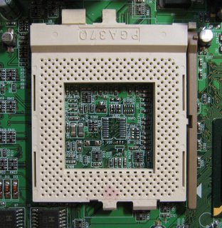
The term CPU socket (or CPU slot) is widely used to describe the connector linking the motherboard to the CPU(s) in certain types of desktop and server computers, particularly those compatible with the Intel x86 architecture.
Most CPU sockets and processors in use today are built around the pin grid array (PGA) architecture, in which the pins on the underside of the processor are inserted into the socket, usually with zero insertion force (ZIF) to aid installation. In contrast to this, several current and upcoming sockets use a land grid array (LGA) in which the pins are on the socket side instead and come in contact with pads on the processor. Slot based processors are cartridge shaped and fix into a slot that looks similar to expansion slots.


List of sockets and slots


Sockets
Socket 1 - 80486
Socket 2 - 80486
Socket 3 - 80486 (3.3 V and 5 V) and compatibles
Socket 4 - Intel Pentium 60/66 MHz
Socket 5 - Intel Pentium 75-133 MHz; AMD K5; IDT WinChip C6, WinChip 2
Socket 6 - 80486
Socket 7 - Intel Pentium, Pentium MMX; AMD K6
Super Socket 7 - AMD K6-2, AMD K6-III; Rise mP6
Socket 8 - Intel Pentium Pro
Socket 370 - Intel Pentium III, Celeron; Cyrix III; VIA C3
Socket 423 - Intel Pentium 41 Willamette core
Socket 463 (also known as Socket NexGen) - NexGen Nx586
Socket 478 - Intel Pentium 4, Celeron, Pentium 4 Extreme Edition1
Socket 479 - Intel Pentium M, Celeron M, Core Duo, & Core Solo
Socket 486 - 80486
Socket 499 - DEC Alpha 21164a
Socket 563 - AMD low-power mobile Athlon XP-M (µ-PGA Socket, mostly mobile parts)
Socket 603 - Intel Xeon
Socket 604 - Intel Xeon
Socket 754 - AMD single-processor systems using single-channel DDR-SDRAM, including AMD Athlon 64, Sempron, Turion 64
LGA 771 (also known as Socket 771) - Intel Xeon
Socket T (also known as LGA 775 or Socket 775) - Intel Pentium 4, Pentium D, Celeron D, Pentium Extreme Edition, Core 2 Duo, Core 2 Extreme, Celeron1
Socket 939 - AMD single-processor systems using dual-channel DDR-SDRAM, including Athlon 64, Athlon 64 FX to 1 GHz2, Athlon 64 X2, Opteron 100-series
Socket 940 - AMD single and multi-processor systems using DDR-SDRAM, including AMD Opteron 2, Athlon 64 FX
Socket A (also known as Socket 462) - AMD Athlon, Duron, Athlon XP, Athlon XP-M, Athlon MP, and Sempron
Socket F (also known as Socket 1207) - AMD multi-processor systems using DDR2-SDRAM, including AMD Opteron2, replaces Socket 940
Socket AM2 - AMD single-processor systems using DDR2-SDRAM, replaces Socket 754 and Socket 9392
Socket 4x4 - Future AMD dual-processor systems using DDR2-SDRAM, allows two dual-core microprocessors side by side (2x AM2 sockets or 2x 1207-pin socket F are rumoured).
Socket P - Future Intel-based, replaces Socket 479 for notebooks (Expected 2007)
Socket S1 - AMD-based mobile platforms using DDR2-SDRAM, replaces Socket 754 in the mobile sector
PAC418 - Intel Itanium
PAC611 - Intel Itanium 2, HP PA-RISC 8800 and 8900
Socket M - Intel Core Solo, Intel Core Duo, Intel Dual-Core Xeon and Intel Core 2 Duo

Slots


Slot 1 - Intel Celeron, Pentium II, Pentium III
Slot 2 - Intel Pentium II Xeon, Pentium III Xeon
Slot A - AMD Athlon
Slot B - DEC Alpha
Slotkets - adapters for using socket processors in bus-compatible slot motherboards
1: The 478 pin socket was introduced because it uses a micro-PGA layout which is physically smaller than the socket 423. Socket 775 was introduced with support for PCI express, DDR2 memory and Intel's version of the AMD64 processor extensions (called EM64T), but also moved to the new Land Grid Array physical layout, where the pins are in the socket rather than on the CPU package, for better electrical performance.
2: These sockets are for CPUs with integrated memory controllers. The 754 pin models have a single memory channel routed through the CPU pins. The 939 pin models have two memory channels, hence the higher pin count. The 940 pin CPUs also have two memory channels but they require registered memory, and most have support for SMP. Sockets F and AM2 are redesigned to support DDR2. The Socket F contains 1207 pins (Added pins speculated to be for more scalability and better power distribution. Socket AM2 has 940 pin-holes but does not support current AMD Opteron processors.
3: The slot packages had two advantages; L2 cache could be installed on the processor package but on a separate piece of silicon, and insertion and removal is simpler and easier. However, it lengthens the path of the traces from the CPU to the chipset and so became unsuitable as clock speeds increased past around 500 MHz. They were therefore abandoned and replaced with Socket A/Socket 370.


Tuesday, November 14, 2006

1394 Firewire

Hardware & Drivers
FireWire

FireWire is one of the fastest peripheral standards ever developed, which makes it great for use with multimedia peripherals such as digital video cameras and other high-speed devices like the latest hard disk drives and printers.

FireWire is integrated into Power Macs, iMacs, eMacs, MacBooks, MacBook Pros, and the iPod. FireWire ports were also integrated into many other computer products dating back to the Power Macintosh G3 "Blue & White" computers. All these machines include FireWire ports that operate at up to 400 megabits per second and the latest machines include FireWire ports that support 1394b and operate at up to 800 megabits per second.

FireWire is a cross-platform implementation of the high-speed serial data bus -- defined by the IEEE 1394-1995, IEEE 1394a-2000, and IEEE 1394b standards -- that can move large amounts of data between computers and peripheral devices. It features simplified cabling, hot swapping, and transfer speeds of up to 800 megabits per second (on machines that support 1394b).

Major manufacturers of multimedia devices have been adopting the FireWire technology, and for good reason. FireWire speeds up the movement of multimedia data and large files and enables easy connection of digital consumer products -- including digital camcorders, digital video tapes, digital video disks, set-top boxes, and music systems -- directly to a personal computer.

In fact, Apple's FireWire technology was honored by the Academy of Television Arts & Sciences, receiving a 2001 Primetime Emmy Engineering Award for FireWire's impact on the television industry.

Celeron vs. Pentium 4

Battling Brothers - Celeron Vs. Pentium 4

All hail the Pentium 4! With its high clock speeds, a wide selection of compatible platforms and a dearth of rival AMD models, Intel has successfully defended its title as the champion in the processor business. Now the low-cost Celeron model has joined the party in the lower-clock-speed segment (up to 1.8 GHz), in order to beat out AMD's models with low prices and high clock speeds. However, in doing that, isn't Intel competing with its own products?

This question deserves some consideration, as Celeron models have always been based on the latest Pentium technology. Prior to the latest model based on the Willamette core, there was a Celeron based on the Tualatin core and one based on the Coppermine core - both processor types were given more cache and a higher FSB speed, and then marketed as Pentium III processors.

The Celeron Mendocino was a different story, since it was the first mainstream processor to have an integrated L2 cache. Intel's first attempt to integrate the L2 cache directly into the processor failed, because the sheer mass of processor rejects drove the manufacturing costs for the Pentium Pro through the roof. While its successor, the Pentium II, also had an integrated L2 cache, the same difficulties prevented it from being integrated directly into the processor core. Instead, Intel integrated the processor onto a small circuit board, added memory components for the L2 cache, wrapped it all up in a plastic box, and dubbed it the "Slot 1." The processor had morphed into a clunky plug-in board that was more expensive than its socket-based rivals.

Once 0.25 µm manufacturing methods were introduced, though, Intel was able to integrate the L2 cache into the core, stepping up performance considerably. The first processor to benefit from this then-innovative technique was the Celeron Mendocino (128 kB L2 cache). It was not until many months later that the second one, the Pentium III with a Coppermine core (256 kB), came out.

Not only did past Celerons have to get by with a smaller L2 cache, but their FSB clock speed was also slower (first 66, then 100 MHz). That's all changed now, with the latest model based on Pentium 4 architecture. So does that, plus its low price tag, make it a viable alternative to the Pentium 4?

Types of Computer Cases

Desktop

Desktop computer cases are for the models of PC that sit on the desk horizontally. As far as computer cases go, desktops have the least amount of choice available on the market. Although the majority of new PC's come with towers or mini towers, some are still built around desktops.

Mini Tower

Most towers are specified by the number of internal drive bays they possess. Mini has 3, midi has 4, and full size towers have 7. These do vary depending on the manufacturer but most can be defined by the number of drive bays.

Full Tower

Full towers normally have 7 drive bays and are the most expensive towers to buy cases for. There are midi towers that are generally 4-5 bays but not all online stores and catalogues separate the two different sizes.

Power Supply Types

Power Supply Types There are two basic types of power supplies. There are AT power supplies, which are older and in older computers, and ATX power supplies, which you will find in virtually every new computer you can buy.

There are two fundamental differences between AT and ATX power supplies. First, the switch mechanism is different. AT power supplies use a normal on-off switch, which directly turns the power supply on or off.

ATX power supplies use a momentary switch which does not directly control the power. Instead, the switch signals the motherboard, which performs one of three actions:

  • If the computer is off, the power supply is turned on (which turns the computer on)
  • If the computer is on, the computer goes into power-saving mode (standby)
  • If the switch is held for more than 4 seconds, the power is cut and the computer turns off.
Because of this difference, ATX power supplies are better for projects that require the second power supply to turn on automatically when the computer is turned on.

The second difference is in the motherboard connector: AT power supplies provide two 6-pin connectors (figure 1), which are easy to insert backwards. The ATX connector is a single 20-pin connector that only plugs in one way (figure 2).

Figures 1 and 2: The difference between AT (left) and ATX (right) motherboard connectors.

Both power supplies provide two types connectors for plugging devices into. These connectors are called Molex connectors, and they come in two sizes (see figure 3 and 4). A power supply will generally have a few of each size.

Figures 3 and 4: Large (left) and small (right) Molex connectors.

There is no difference between the two sizes other than the size itself. Both sizes provide the same amount of power to whatever device is plugged into it (12V and 5V). The small Molex connectors are generally used only for floppy drives. Large Molex connectors power hard drives, CD/DVD drives, and many fans and lights as well.

Note: You can purchase large and small Y-adapters if you run out of Molex connectors. Be careful when using the Y-adapters however, because if your power supply does not have enough power for all the devices attached (especially true for older, lower-wattage supplies), you can damage it.